I have collected a lot of info about various analyzers, so now I decided to publish some on this page. I was interested in devices which can measure parameters of antennas; this is why scalar network analyzers are not in my list. Also, I have not listed very simple (like plain SWR bridges) and very complex (professional instruments made by Agilent, Anritsu, etc.) analyzers. I have put my comments under links to manufacturer or author websites.
Analyzers based on diode detectors
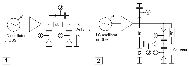
The RF signal from LC oscillator or DDS is amplified and fed through the resistor (fig. 1) or the resistive bridge (fig. 2) to the antenna. By using diode detectors and analog-to-digital converters built into the microcontroller, DC voltage is measured in several points. Some analyzers have automatic gain control circuit to maintain stable RF signal.
- VK5JST analyzer
Up to 30 MHz. A handheld device with text-only LCD. To tune to the working frequency, a variable capacitor is used. The frequency is displayed on the LCD. This analyzer was manufactured as a “do-it-yourself” kit and is quite popular. - MFJ analyzers
Most junky and (at the same time) very popular devices. HF/VHF/UHF. LC-oscillator plus frequency counter which displays data on the LCD. Additionally, needle indicators are placed on the front panel. - UT2FW antenna analyzer
DDS-based HF analyzer with text-only LCD. - AA-330 (RX3ADU)
DDS-based HF analyzer with text-only LCD. - AEA Technology 140-525 Antenna Analyst
VHF analyzer with PLL-based synthesizer and graphical LCD. - AA-908
DDS-based HF analyzer with text-only LCD. - Palstar ZM-30
HF analyzer (up to 30 MHz) with DDS and text-only LCD. According to the RadCom, this analyzer is based on AA-908. - SARK100 aka MINI60
DDS, 16×2 LCD, computer connection.
The sign of reactance cannot be detected with analyzers from this group. Additionally, these analyzers require calibration before use to take into account parameters of diodes.
Analyzers based on logarithmic amplifier detector (on a working frequency)
- RigExpert AA-520 (also: AA-500)
Up to 520 (500) MHz. Outputs of two PLL-synthesizers are mixed to produce working frequency with tiny increments.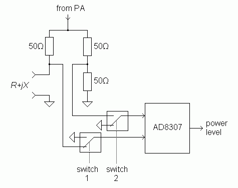
The detector is switched between various points of the resistive bridge. A calibration is not required. The sign of reactance is not detected.
Analyzers with logarithmic amplifier and phase detector (on a working frequency)
- MiniVNA
A quite popular miniature analyzer, up to 180 MHz. Works only with a computer.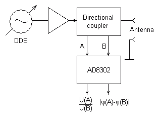
DDS, directional coupler, AD8302-based detector (which outputs DC voltages proportional to amplitude ratio and phase difference of two signals taken from the coupler). The sign of reactance is not detected.
- MAX6
This device can be called a portable version of the MiniVNA. Added: graphical LCD, keypad, battery, also SD/MMC card and infrared remote control support. Awful user interface. - OH8LQ analyzer
Portable version of the MiniVNA with text-only LCD. - AVR Embedded Antenna Analyser
Up to 60 MHz, an electronic project at Circuit Lake. - T100 (Times Technology)
144 and 430 MHz. Very compact and modern device with graphical LCD. PLL-based oscillator, directional coupler, AD8302 detector.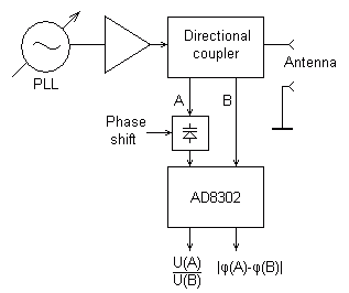
The reactance sign is determined by shifting the phase of the signal at one of the detector inputs. A varicap is used for this purpose, accepting control voltage from the microcontroller (from a lookup table built during the calibration procedure). A user interface is a little bit “dumb”, but the most inconvenient part of this analyzer is it SMA connector. Fortunately, they include N and BNC adapters in the package.
- RigExpert AA-230, AA-230PRO (also: AA-200)
Up to 230 (200) MHz. Dual DDS: one of its channels is fed (via the amplifier) to the resistive bridge, while the second channel (with 0 or 90-degree shift) is wired to one of the inputs of the AD8302 detector. The other input accepts (via the electronic switch) signals from the left or the right side of the bridge.
Calibration is not required. The sign of reactance is detected.
- TAPR VNA
Up to 100 MHz. Dual DDS, directional coupler, 2xAD8302 detectors. Works with computer only. The principle of operation is similar to what AA-230 has. The sign of reactance is determined. - VR2VNA
UHF analyzer project. The author periodically adds new articles to his website.
Analyzers based on super-heterodyne receiver principle
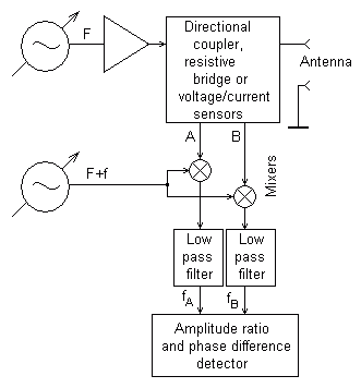
The basic structure of an analyzer based on a single-conversion superheterodyne receiver principle. Frequencies of two oscillators differ by the value of the IF.
- Array Solutions analyzers
HF/VHF (up to 180 MHz), 2xDDS, intermediate frequency = 1 kHz. Works with PC only. Calibration is required before use. A very wide range of the measured impedance. The “AIM UHF” model has a wider frequency range (up to 1 GHz) and is using alias frequencies (as in the DG8SAQ analyzer – see below). - DG8SAQ analyzers
HF/VHF/UHF (up to1.3 GHz), 2xDDS, audio intermediate frequency is fed to the PC via its sound card. For high frequencies (higher than DDSs can produce) a combination of alias frequencies is used (there is no low pass filters at the outputs of the DDS chips). Also, different clock frequencies are used for two synthesizers to let this method work. - Scotty’s Modularized Spectrum Analyzer (MSA)
Originally, it is a spectrum analyzer (up to 1000 MHz), which can be converted to the vector network analyzer (which may be used for antenna measurements, an external hardware is needed). The working frequency is produced by mixing outputs of two microwave oscillators.The first IF is 1013.3 MHz, the second one is 10.7 MHz. At the second IF, amplitude (logariphmic detector is used) and phase difference with reference signal (by using a trigger-based 360-degree phase detector) are measured. - SARK-110
Color touch screen, up to 200 MHz. - RigExpert AA-30 and RigExpert AA-54
These analyzers use harmonics of DDS outputs to produce higher frequencies. A single audio frequency channel is used, so there is no need for calibration to obtain good measurement results.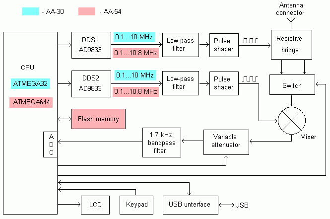
- RigExpert AA-170, RigExpert AA-600, RigExpert AA-1000 and RigExpert AA-1400
Same principle, but larger frequency range (up to 170/600/1000/1400 MHz).
All analyzers from this group can determine sign of reactance.
Analyzers based on direct conversion receiver principle
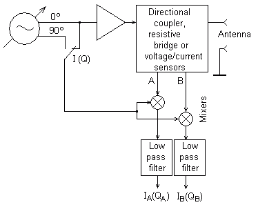
The basic structure of an analyzer based on direct conversion receiver principle. Several techniques may be used to form 90 degree shifted signals at the oscillator output: for instance, additional DDS or a phase shift network in PPL-base synthesizers. This analyzer outputs DC voltages proportional to in-phase (I) and quadrature (Q) components of A and B channels.
- BX-110 (DL1SNG)
Up to 160 MHz, dual DDS: the first channel if fed (via the amplifier) to the resistive bridge, the second channel goes to the mixer (with 0 or 90 degree shift). The RF inputs of the mixer are connected to the bridge diagonally. To maintain constant amplitude and phase of the signal at the bridge, operational amplifiers with low output impedance are used. Calibration is required before use. - N2PK analyzer
Very popular analyzer, “a dream of the experimenter”. Developed with love. Up to 60 MHz in the basic version (up to 500 MHz when using a transverter). DDS oscillators (90 degree phase shifted), 24-bit ADC. A very wide range of the measured impedance. - PA1ARE
A quite simple “do-it-yourself” analyzer with text-only LCD. Up to 30 MHz. A PLL-based oscillator signal is mixed with a quartz oscillator outputs (0 and 90-degree). Resulting signals are wired (via switching diodes) to the VFO input of the mixer. Outputs of voltage and current sensors are fed (also via switching diodes) to the RF input of the mixer. The 10-bit ADC converts DC voltage from the mixer output. - Experimental (unnamed) HF analyzer which does not contain expensive electronic components.
- Network analyzer 150MHz by Jacques Lacroix. Based on ideas of N2PK. A quite simple frequency multiplier build around microstrip line filter can be used as a source of the DDS reference signal.
- MiniVNA PRO
Two-port analyzer with 90 dB dynamic range. Built-in Bluetooth module for remote operation. - SWR-1 (EU1ME)
1 – 30 MHz, a small portable analyzer
All analyzers from this group can determine sign of reactance.
I do not have much information about these analyzers
- Autek Research analyzers
HF and VHF analyzers, 7-segment LCD. - Bird analyzers
- SWR ONE (COMM-connect)
10-2700 MHz. SWR only. - FeatureTech analyzers
Something similar to MFJ. - LA Techniques Ltd. analyzers
Vector network analyzers, up to 3 GHz. - ANA 2700 (Meret Optical)
Up to 2.7 GHz. - Bode 100
Up to 40 MHz. Analyzer for professional use, works with a computer only. - Измеритель КСВН панорамный Р2-135
Up to 2.4 GHz. Large graphical LCD. Very dumb design of the enclosure. - TimeWave TZ-900 (AntennaSmith)
Up to 55 MHz. Modern handheld device with color graphical LCD. - Tomco TE1000
Up to 150 MHz. Desktop device with very wide impedance range. - Vectronics SWR-584B
Looks like an MFJ clone. - VNA-3B («Стоянов и Граматиков»)
Several versions of analyzers, up to 6 GHz. Graphical LCD. - WE-030A/B, WE-520A, WE-1002A, WE-2705P (Waterbeach Electronics Ltd)
Up to 30/520/1000/2700 MHz, a handheld device with graphical LCD. DDS-based oscillator (DDS+PLL in VHF models). - Modern AEA Technology analyzers
Up to 2.5 GHz. Graphical LCD. They are using the same enclosure (called “a brick” by the users) as in previous generation devices. Also, 8 (eight!) AA-size batteries are used to power up these analyzers. - LISIC ATS3505B
1 – 33 MHz, USB or Bluetooth connection. - MiniVNA Tiny
1 – 3000 MHz, USB connection. See the miniVNA Tiny – a few experiments article. - MetroVNA Pro
1 – 185 MHz, USB or Bluetooth connection. - FA-VA MK II
50 kHz – 160 MHz, graphical LCD - iPortable iP30Z, iP60Z
400 kHz – 35 (or 60) MHz - KVE60C, KVE520
0.5 – 60 (KVE60C) and 3 VHF/UHF bands (KVE520), color LCD - KC901H
Up to 3 GHz, scalar network analyzer, color LCD
Denis Nechitailov, UU9JDR
Last updated: 15.09.2014
P.S. Any changes? Drop me an email, please.
